Installation instructions for the IPP
short throw shifter
1996 to 2001 Audi A4
1998 to 2001 VW Passat (with threaded
shifter knob)
DISCLAIMER:
Innovative
Performance Products will assume no liability for any injury resulting from the
misinterpretation of the installation instructions. Follow the instructions at
your will.
Before starting the installation of the short throw shifter please
read the complete instructions as well as the accompanying pictures. You can also choose to print these
instructions to aid in the installation process.
Tools
needed for the installation:
·
1/4 inch (works best because you can’t over
tighten with it) or 3/8 inch drive ratchet (comes in most tool sets)
·
4 or 6 inch extension (comes in most tool sets)
·
10mm socket (comes in most tool sets)
·
13mm socket (if your car
HAS push-down reverse from the factory) (comes in most tool sets)
·
T-25 Torx driver (if your
car is a late 1999 or newer A4/ all Passats) (comes in most tool
sets), or
·
5mm hex driver, or a 5mm Allen key (if your car is an early 1999 or older A4) (you
will need to use the locking pliers to turn the Allen key)
·
6mm hex driver, (looks like an Allen key,
but fits on a ratchet end), or an 6mm Allen key ( you will need to use the
locking pliers to turn the Allen key)
·
10mm combination wrench (gear wrenches work great)
·
Rubber hammer (if your
car does NOT have push-down reverse from the factory)(best if it is
a rubber mallet or plastic hammer)
·
Locking pliers (Vice-grips)
·
Snap ring pliers (flat-head screwdriver will work,
but you need to be careful not to stab your finger when trying to pry on the
snap ring to remove it)
Where applicable in the installation instructions, the tool being
used is described in red text.
Early 1999 and older
A4s/VW Passats came equipped with the push-down shifter. All late 1999, as well
as 2000 and newer models did not have this feature. Although some of the parts
pictured herein may look different from yours, they will all follow the same
removal procedures listed below.
1.
Place
the car in neutral and set the parking brake firmly.
2.
Remove
your shifter knob by turning it in a counter-clockwise direction.
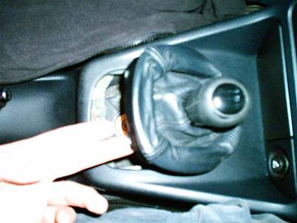
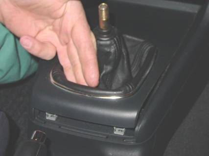
3.
Remove
the shifter boot by prying up on the rear side (closest to the handbrake) with
your fingers. (See picture below).
|
Older shifter boot
style (1997 Audi A4 shown, VW Passat similar) |
Newer Shifter boot
style ( late 1999 Audi A4 shown) |
|
|
|
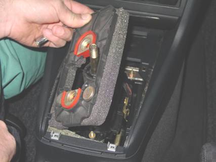
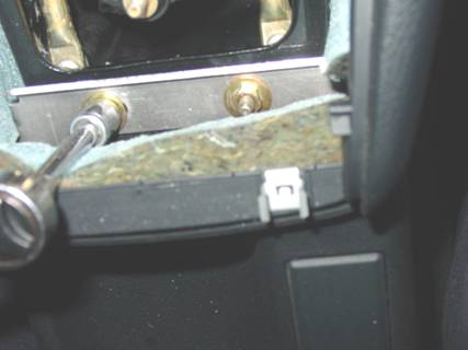
4. Remove the two nuts holding the
dampening baffle to the shifter linkage, and then remove the dampening baffle
to expose the shifter linkage assembly.
·
On
early 1999 and older A4s/Passats, one nut will need to be removed using a 13mm
socket, the other a 10mm socket.
·
On
late 1999 and newer A4s/Passats, both nuts will need to be removed using a 10mm
socket.
|
Dampening baffle nuts
(Late 1999 A4 shown) |
Removing dampening
baffle to expose shifter linkage assembly |
|
|
|

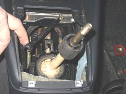
5.
Next,
remove the four 10mm nuts that fasten the shift linkage to the body of the
vehicle. The nuts closest to the rear of the console can be accessed with a regular
¼ inch drive ratchet, extension, and a 10mm socket. The front nuts must
be removed using a 10mm box-end wrench. On older cars, this is a little more
difficult, due to the smaller opening of the shifter boot. PATIENCE IS KEY HERE.
During the removal of these
four nuts, be very careful not to drop any of them into either side of the
driveshaft tunnel, otherwise you may need to remove the centre console to get
them out.
|
Front nuts removal (10mm combination
wrench) (shown on late 1999
Audi A4) |
Rear nuts removal (¼”
drive ratchet, extension, and 10mm socket) (shown on late 1999
Audi A4) |
|
|
|
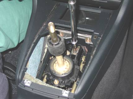
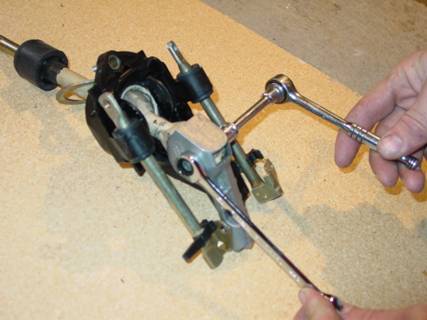
6.
The
complete shift linkage and housing should now be loose. You can now lower the
housing downward to rest on the driveshaft.
7.
With
a 6mm Allen wrench loosen the sift linkage brace bolt. It is installed from the
factory with Loc-Tite, and may be on very tight. At this time you should also
loosen the other 6mm Socket-head cap bolt that fastens the shifter linkage to
the selector rod. Note the position of the rectangular aluminum washer.
|
Shifter brace bolt
removal
(6mm hex driver,
3/8” drive ratchet, and 6”extension) |
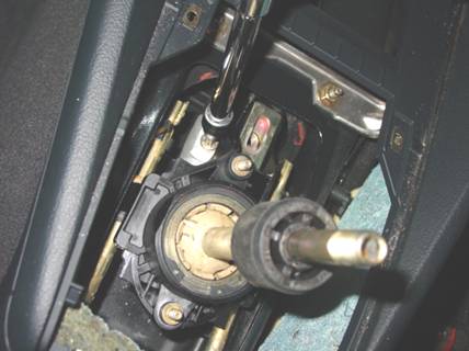
Shifter linkage to selector
rod bolt and rectangular washer (aluminum) (6mm hex driver,
3/8” drive ratchet, and 6”extension) |
|
|
|
8.
Remove
the four bolts or screws holding the shift linkage to the shift linkage
housing. The housing can be shifted back and forth to gain access to the rear
or front screws/bolts.
·
On
early 1999 and older A4s, remove the four 5mm Socket head cap bolts (Allen
head).
·
On
all late 1999 and newer A4s, and all Passats, remove the four T-25 Torx screws.
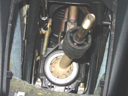
|
Torx screws (three can
bee seen in this picture) (late 1999 A4 shown)
(T-25 Torx driver,
3/8” drive ratchet, and 6” extension) |
|
|
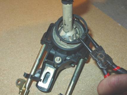
9.
With
Torx screws/ Allen bolts have been removed, the
shifter linkage can now be removed from its housing. To do this you will need
to wiggle it around. Once the shift linkage is out of the car, it can be
disassembled.
10.
Remove
the shifter rod to shifter fork bolt and nut using a 10mm wrench and socket.
Slide the two pieces apart.
|
Shifter Fork to
shifter Rod bolt (10mm combination wrench,
10mm socket, ¼” drive ratchet, extension not needed) |
|
|
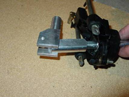
11.
Remove
the snap ring holding the shaft to the shifter linkage. If you do not have a
pair of snap ring pliers, the snap ring can be removed using a flat screw
driver. It is a good idea to have someone to help you do this. THERE IS
|
Early 1999 and older
A4/Passat shifter shaft snap ring |
Late 1999 and newer
A4/Passat snap ring removal (Snap ring pliers) |
|
|
|
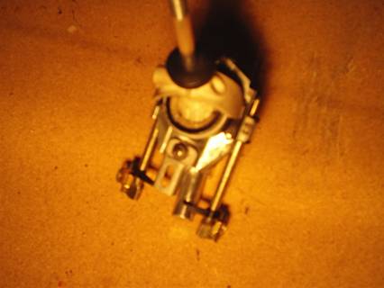
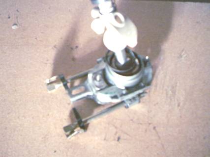
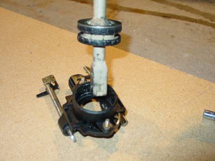
12.
Place
the shifter shaft vertical on a solid surface, and apply downward force to the
shifter assembly.
·
This
will separate the shifter shaft from the shifter assembly on later 1999 and
newer A4s/Passats.
·
On
early 1999 A4s/Passats, this will separate the shifter shaft from its socket.
|
Early 1999 and older
A4/Passat shifter assembly (separated) |
Late 1999 and newer
A4/Passat shifter assembly (separated) |
|
|
|
Steps
13, 14, and 15 apply only to late 1999 and newer A4s/Passats.
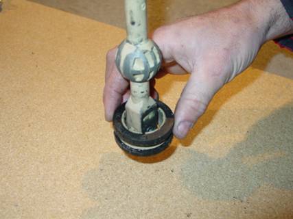
13.
Separate
the shifter ball from the ball socket in the same manner that the shifter shaft
was separated from the shifter assembly (see step 12)
|
Separating the
shifter ball from its socket |
|
|
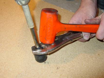
14.
Remove
the rubber isolator from the shifter shaft. This procedure is harder then it
looks. Over time, the rubber “sticks” to the shaft. We recommend
you use plenty of lubrication (anything from water to Wd-40) to ease the
removal of this piece. We found that the simplest way of removing the isolator
was:
·
Clamp
it lightly (so as not to squeeze it on the shaft) with vice-grips, and
·
Then
tapping it with a plastic or rubber hammer. Protect the shaft threads by placing
the shaft on a piece of wood when hammering.
|
Separating the
rubber isolator from the shaft
(Locking pliers
and plastic hammer) |
|
|
15.
Transfer
the rubber isolator to the new shaft. Lightly coat the shaft with the provided
grease. It should slide on the new shaft without any problems.
The
following applies to all 1996 to 2001 A4s, and all VW Passats.
16.
Using
the supplied synthetic grease, thoroughly coat the inside of the shifter ball
socket. Leave a small quantity aside to be used later.
17.
Re-install
the shifter shaft into the shifter assembly in the reverse procedure of steps
12-15.
18.
Thoroughly
coat the bottom of the shaft and insert the provided bushing into the shaft.
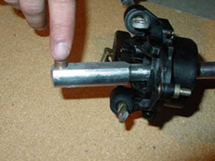
19.
Assemble
the shaft with the shifter fork (see picture).
NOTE:
The shifter fork is tapered, and is widest at the top. The shaft must be
inserted exactly as pictured, or you will risk scratching the shaft’s
surface.
ALSO
NOTE THE ORIENTATION OF THE SHIFTER FORK ONTO THE SHAFT. It can only be
installed in this manner.
|
Inserting bushing
into shaft |
Inserting shaft into
shifter fork |
|
|
|
20.
Insert
the bolt through the shifter fork in the same manner that the OEM bolt was
inserted in the OEM fork. (From left to right when looking at the shifter in
its installed position.
21.
Lightly
tighten the provided nut onto the bolt using a 7/16 wrench. DO NOT OVERTIGHTEN. You should tighten
the nut until a very light resistance is felt when rotating the shifter fork on
its bushing. The Nylon insert prevents the nut from loosening itself off.
22.
The
rest of the installation is the reverse of removal. Start by lowering the
complete shifter assembly back into the shifter housing.
23.
When
installing the four T-25 Torx screws, or 5mm Allen bolts, take care not to drop
them into the housing, as this will be a definite set-back. You can use a
little bit of tape to hold the screw to the screwdriver. DO NOT OVERTIGHTEN.
24.
Replace
the socket -head cap bolt that fastens the shifter linkage to the selector rod.
Don’t forget the large rectangular washer. Do not tighten the bolt at
this time. It will need to be loose for adjustment of the shifter.
25.
Replace
the shifter brace bolt (6mm Socket-head cap bolt), and leave it loose as well.
This bolt will enable you to adjust the complete shifter assembly back and
forth to suit your preference.
26.
You
are now ready to re-attach the shifter housing to the body of the car. There is
one or two brackets (one on earlier models, two on later model A4s) on the
centre console. The bolts on the shifter housing must be guided through these
brackets before the nuts are threaded on to them.
27.
Thread
the nuts on to the housing bolts and tighten them by hand.
28.
Tighten
the two front nuts using the box-end wrench. The rear nuts can be tightened
with a ratchet. Do not over tighten the nuts; the specified torque is 15 ft-lb.
Adjustment instructions
NOTE: Adjustment is necessary to
ensure a properly aligned shifter.
While
performing the adjustment, it is also necessary to check for interference
between the shifter fork bolt and the shifter housing. Ensure that you can freely move the
shifter to the left-most and right-most position without it ever hitting the
sides of the housing.
Holding
the shifter shaft vertical, before tightening the shifter linkage to selector
rod bolt (the one with the rectangular washer), is the proper procedure for
ensuring there will be no interference issues. If there is some contact,
determine which side it is hitting, and move the shifter to the opposite side.
For
instance, if the shifter makes contact when you move it into first or second
gear, then you will need to move the shifter closer to the right side of the
housing, and vice versa. To do this you will need to loosen the lower adjustment bolt (the one with the big
rectangular washer), and move the shifter to the opposite side that it hits
when you are shifting. Hold the shifter there while re-tightening the bolt. The
shifter should be sitting almost perfectly vertical when it is adjusted
properly.
1.
Adjust
the seat of the car to where you normally have it when you drive. Temporarily
thread the shift knob onto the shaft. You can slide the entire linkage back and
forth to where you like it.
2.
You
can now lightly tighten the 6mm linkage brace bolt.
3.
You
can adjust the shifter shaft back and forth and lightly tighten the selector
rod 6mm Socket-head cap bolt. If the distances between the shifting of the
gears are uneven, loosen the selector shaft Socket head cap bolt (the lower
one) and readjust until the distances between neutral and first gear, are close
to the distances between neutral and second gear. Make sure this bolt is tight
after the adjustment is complete or else it will move while you are driving.
Repeat this procedure until you get the best feel for the shift between all
gears. This can take several tries, but it is very important to have a good
feeling shift.
4.
When
you are satisfied with the shifter feel, finish tightening the selector rod
bolt. The specified torque is 25 ft-lb. If you use a ¼ inch drive
ratchet, you can tighten it to its fullest. The residual Loc-Tite will keep the
threads locked.
5.
Install
the baffle and its 10mm and/or 13mm nuts.
6.
Replace
the shifter boot and knob, and you are ready to go.
We hope we covered every aspect of the
installation. If you have any questions, please contact us.
You will enjoy years of trouble-free,
great feeling shifts.